DESIGN PROCEDURE FOR BEVEL GEARS From the requirements choose suitable materials for pinion and gear tooth profile and pressure angle are selected. Consulting Table 53 knowing the gear ratio i choose the suitable material. Bevel gear design procedure.
Bevel Gear Design Procedure, Thermal capacity materials -forces and stresses efficiency estimating the size of the worm gear pair. UNIT IV DESIGN OF GEAR BOXES. I recommend that you play around and try to create different cogs and gears.
 Figure 16 From Design And Analysis Of A Spiral Bevel Gear Semantic Scholar From semanticscholar.org
Design procedure for bevel gear. Design of peripheral structures of gears. Calculation of gear ratio i. Basic understanding of the design elements of bevel and hypoid gears.
Speed of pinion and gear are Np 500 RPM and Ng 250 RPM respectively.
These gears are also easier to design to fit given centre distances because there are more parameters that can be rearranged. These gears are also easier to design to fit given centre distances because there are more parameters that can be rearranged. Select the number of teeth for the pinion and the g. Where N A and N B speed of the driver and driven respectively and Z A and Z B Number of teeth on driver and driven respectively. γ 1 γ 2 Σ γ 1 2 in case of a 90 shaft angle. Bevel gears should be fastened to the shaft with keys and set screws taper pins step shafts etc.
Read another article:
 Source: sdp-si.com
Consulting Table 53 knowing the gear ratio i choose the suitable material. In this tutorial you will find a step by step guide on how to create a bevel gear in SolidWorks by using 3D features. Design procedure for Bevel Gear. UNIT IV DESIGN OF GEAR BOXES. Helical Gear Calculations Crossed Helical Gear Meshes And Bevel Gearing Sdpsi.
 Source: geartechnology.com
Design procedure for Bevel Gear. F Problem Statement and Solution Problem. Since almost all mechanical designs use gears and cogs they are very useful to know. To optimize the performance of any two bevel gears the gears must be positioned together so that they run smoothly without binding andor excessive backlash. A Practical Approach For Modeling A Bevel Gear Gear Technology March April 2015.
 Source: researchgate.net
Thermal capacity materials -forces and stresses efficiency estimating the size of the worm gear pair. As the popularity of five-axis CNC machine tools and multi-axis CAM software has increased such tools are now being used to manufacture these types of. In this series we explain how to design gears and peripheral parts according to procedures using simple mechanisms. Where N A and N B speed of the driver and driven respectively and Z A and Z B Number of teeth on driver and driven respectively. Concept And Reality Flowchart For Straight Bevel Gear Design Download Scientific Diagram.

Schultz All rights reserved. Where NA and NB speed of the driver and driven respectively and ZA and ZB. This paper describes the design of a straight bevel gearset with the objective of minimizing the enclosed volume. You cannot install bevel gears in the same manner as spur and helical gears and expect them to behave and perform as well. How To Determine The Module Of A Spiral Bevel Gear Set Quora.
 Source: slideplayer.com
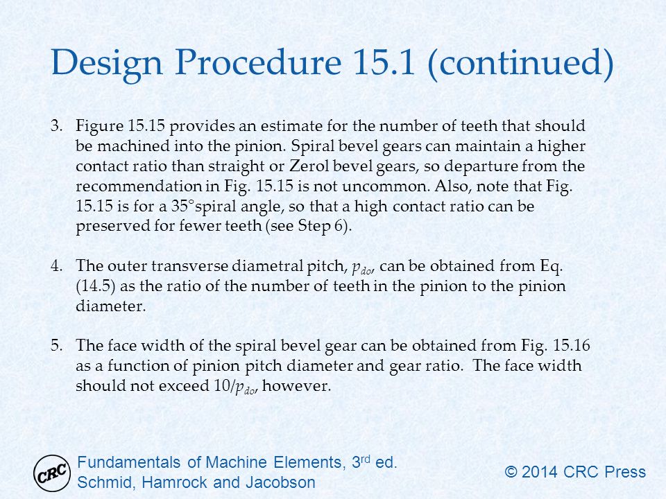
Average module mav can be calculated based on the beam strength using the equation DESIGN PROCEDURE FOR BEVEL GEARS 5. Check spur gears strength. Where NA and NB speed of the driver and driven respectively and ZA and ZB. Estimating the dimensions of pair of straight bevel gears. Chapter 15 Helical Bevel And Worm Gears Ppt Video Online Download.
 Source: slideplayer.com
Where N A and N B speed of the driver and driven respectively and Z A and Z B Number of teeth on driver and driven respectively. In this tutorial you will find a step by step guide on how to create a bevel gear in SolidWorks by using 3D features. The main disadvantage of the helical gear -. October 1 1990 - AGMA. Chapter 15 Helical Bevel And Worm Gears Ppt Video Online Download.
 Source: semanticscholar.org
Miter bevel gears are a special class of bevel gear where the gear shafts intersect at 90 each of the two gears has a 45 pitch angle and both gears have the same number of teeth ie the gear ratio is 11. The objective of this project was to develop an automated process for modeling spiral bevel gears to reduce gear design time. Where N A and N B speed of the driver and driven respectively and Z A and Z B Number of teeth on driver and driven respectively. F Problem Statement and Solution Problem. Figure 16 From Design And Analysis Of A Spiral Bevel Gear Semantic Scholar.
 Source: youtube.com
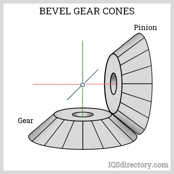
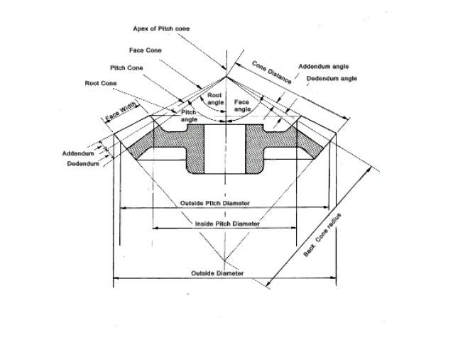
All bevel gears are designed using a reference right cone called the pitch cone The pitch cone is used as a basis for describing all other geometric entities of the bevel gear. Speed of pinion and gear are Np 500 RPM and Ng 250 RPM respectively. Helical gears are superior to spur gears in most applications especially where noise must be kept to a minimum or the pitch line speed is in excess of 10 ms. Design a pair of bevel gear which is used to connect two shaft at right angles and transmit P 50 kW power from an induction motor to a conveyor belt. Design Of Bevel Gear I Youtube.
 Source: youtube.com
Exercises in calculating gear dimension sheets the use of Gleason time sharing computer programs and the evaluation of resulting stress data. The sum of the pitch angles of spiral bevel gears is equal to the shaft angle. Fundamentals of Bevel Gear Design. These gears are also easier to design to fit given centre distances because there are more parameters that can be rearranged. Bevel Gear Design Procedure Steps How To Calculate Module Of Bevel Gear Youtube.
 Source: researchgate.net
Calculation of gear ratio i. Design shapes of spur gears. Self-published by Charles D. Check spur gears strength. Procedure For The Geometrical Synthesis Of A Straight Bevel Gear Iso Download Scientific Diagram.
 Source: iqsdirectory.com
Design a pair of bevel gear which is used to connect two shaft at right angles and transmit P 50 kW power from an induction motor to a conveyor belt. Helical gears are superior to spur gears in most applications especially where noise must be kept to a minimum or the pitch line speed is in excess of 10 ms. Gear theory terminology selection of gear size tooth design parameters and cutting methods. Design procedure for Bevel Gear. Bevel Gear What Is It How Does It Work Types Uses.
 Source: youtube.com
Schultz Beyta Gear Service. Is outlined as follows. Helical gears are superior to spur gears in most applications especially where noise must be kept to a minimum or the pitch line speed is in excess of 10 ms. Calculation of gear ratio i. Bevel Gear Design Procedure Steps How To Calculate Module Of Bevel Gear Youtube.
 Source: sdp-si.com
Select the number of teeth for the pinion and the g. F Problem Statement and Solution Problem. The objective of this project was to develop an automated process for modeling spiral bevel gears to reduce gear design time. Consulting Table 53 knowing the gear ratio i choose the suitable material. Helical Gear Calculations Crossed Helical Gear Meshes And Bevel Gearing Sdpsi.
 Source: studylib.net
Self-published by Charles D. Bevel Gear Design Procedure - YouTube. Design a pair of bevel gear which is used to connect two shaft at right angles and transmit P 50 kW power from an induction motor to a conveyor belt. About Press Copyright Contact us Creators Advertise Developers Terms Privacy Policy Safety How YouTube works Test new features Press Copyright Contact us Creators. Design And Analysis Of A Spiral Bevel Gear.
 Source: slideshare.net
Bevel gears are most often mounted on shafts that are 90 degrees apart but can be designed to work at other angles as well. Beyta Gear Service Charles D. DESIGN PROCEDURE FOR HELICAL GEAR. Where NA and NB speed of the driver and driven respectively and ZA and ZB. Introduction Design Of Bevel Gears.


