For any network that have coupling capacitors the source and load resistance do not affect the dc biasing levels. Differential amplifiers can be made using one opamp or two opamps. Bjt amplifier design tutorial.
Bjt Amplifier Design Tutorial, The BJT is a three terminal device and it comes in two different types. For any network that have coupling capacitors the source and load resistance do not affect the dc biasing levels. First you will examine the S-parameter model of the transistor and analyze its DC bias circuit.
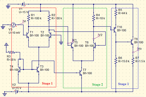 Design And Analysis Of An Operational Amplifier With Bjt Transistors Using The Qucs Simulator Steemit From steemit.com
Re is actually two resistors in series one of which will be call Rg and is called the gain resistor since it controls the voltage gain or amplification. The npn device has. This module shows how to simply calculate the values needed to make a working amplifier that has correct class A bias as described in. The BJT is a three terminal device and it comes in two different types.
Amplification of AC signal can be only done in active region of transistorTo operate transistor in active region Q-point need to be fixed at the center of DC load lineThe red line in the graph indicates DC load lineFixing Q-point at center of DC load line gives maximum amplificationTo fix Q-point at the center of DC load line designing of CE amplifier with correct choosing of resistor and.
There are two pn junctions in the transistor. Rc is called the collector resistor and Re the emitter resistor. Terminals are base-emitter collector and base. Configuration and explore its use in fundamental signal shaping and amplifier circuits. In this tutorial you will build an RF amplifier using a high frequency bipolar junction transistor BJT with lumped elements. Maximize gain G and linearity IIP3 Reduce DC power P DC conflict with F and IIP3 FFMIN Rn Gs YsYsopt 2 FoMLNA G IIP3 f F1 PDC.
Read another article:
 Source: theengineeringprojects.com
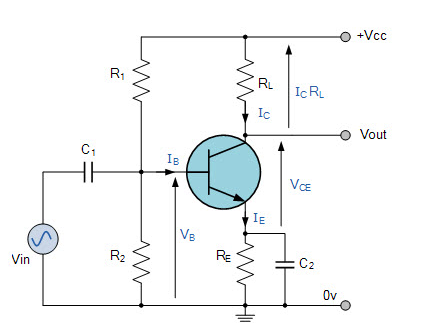
Terminals are base-emitter collector and base. Heres a simple 100 watt amplifier circuit where the output power devices can be seen configured in an source follower design which is an mosfet equivalent of a BJT emitter follower. Common Base BJT Amplifier. In this tutorial you will build an RF amplifier using a high frequency bipolar junction transistor BJT with lumped elements. Common Emitter Bjt Amplifier In Proteus The Engineering Projects.
 Source: theengineeringknowledge.com
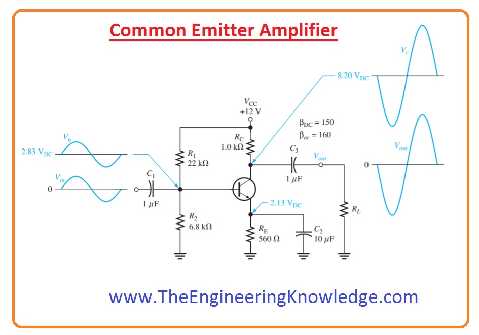
Terminals are base-emitter collector and base. The BJT is fabricated with three separately doped regions. Design Example Amplifier Input and Output Impedances. In this tutorial you will build an RF amplifier using a high frequency bipolar junction transistor BJT with lumped elements. Common Emitter Amplifier The Engineering Knowledge.
 Source: emagtech.com
Design goal Minimize the noise of the amplifier for a given signal source impedance to approach transistor minimum noise figurefactor NF MIN F MIN Input and output matching to source and load. Design Example Amplifier Input and Output Impedances. We also learnt that the transistor junctions can be biased in one of. In this tutorial you will build an RF amplifier using a high frequency bipolar junction transistor BJT with lumped elements. Basic Tutorial Lesson 7 Analyzing The Frequency Response Of Multistage Bjt Amplifiers Emagtech Wiki.
 Source: emagtech.com
Then you will calculate the port characteristics of the amplifier and verify its matching networks. 201 shows a class A common emitter amplifier but without its component values. Heres a simple 100 watt amplifier circuit where the output power devices can be seen configured in an source follower design which is an mosfet equivalent of a BJT emitter follower. Ositive type with the most commonly used transistor type being the. Rf Tutorial Lesson 9 Designing A Distributed Rf Bjt Amplifier Emagtech Wiki.
 Source: tutorialspoint.com
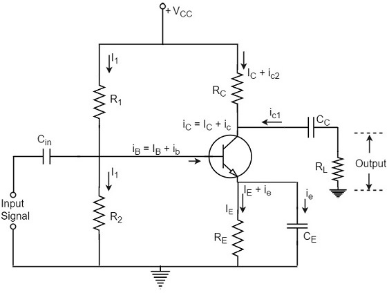
Design goal Minimize the noise of the amplifier for a given signal source impedance to approach transistor minimum noise figurefactor NF MIN F MIN Input and output matching to source and load. Laker based on P. Re is actually two resistors in series one of which will be call Rg and is called the gain resistor since it controls the voltage gain or amplification. Amplification is process through which weak input signal is amplified. Basic Amplifier.
 Source: electronics-tutorials.ws
Maximize gain G and linearity IIP3 Reduce DC power P DC conflict with F and IIP3 FFMIN Rn Gs YsYsopt 2 FoMLNA G IIP3 f F1 PDC. The BJT symbols and their corresponding block diagrams are shown on Figure 1. Re is actually two resistors in series one of which will be call Rg and is called the gain resistor since it controls the voltage gain or amplification. In this tutorial you will build an RF amplifier using a high frequency bipolar junction transistor BJT with lumped elements. Common Emitter Amplifier Tutorial.
 Source: electronics-tutorials.ws
The proper engineers way of designing this is by use of feedback. Abstract-This project explores the robust design of amplitude modulation and demodulation using BJT Amplifier and Diode detector Considering the difficulties faced by the designer in terms of hardware for designing such systems we have used a system that uses less hardware for this processWe have written the ngspice code for the modulator and demodulator as per the circuit diagram and. Or BJT comes in two basic forms. You basically make a crude amplifier with a high gain and enough bandwidth and use feedback to get the gain you actually want. Bipolar Transistor Tutorial The Bjt Transistor.
 Source: emagtech.com
Configuration and explore its use in fundamental signal shaping and amplifier circuits. Amplification is process through which weak input signal is amplified. Differential amplifiers have high common mode rejection ratio CMRR and high input impedance. ESE319 Introduction to Microelectronics 2008 Kenneth R. Basic Tutorial Lesson 7 Analyzing The Frequency Response Of Multistage Bjt Amplifiers Emagtech Wiki.
 Source: pinterest.com
The npn device has. That becomes possible due to the many emitter follower stages involved within an amplifier circuit. Configuration and explore its use in fundamental signal shaping and amplifier circuits. Design goal Minimize the noise of the amplifier for a given signal source impedance to approach transistor minimum noise figurefactor NF MIN F MIN Input and output matching to source and load. Common Emitter Configuration Transistors Electronic Engineering Electronics Components.
 Source: instructables.com
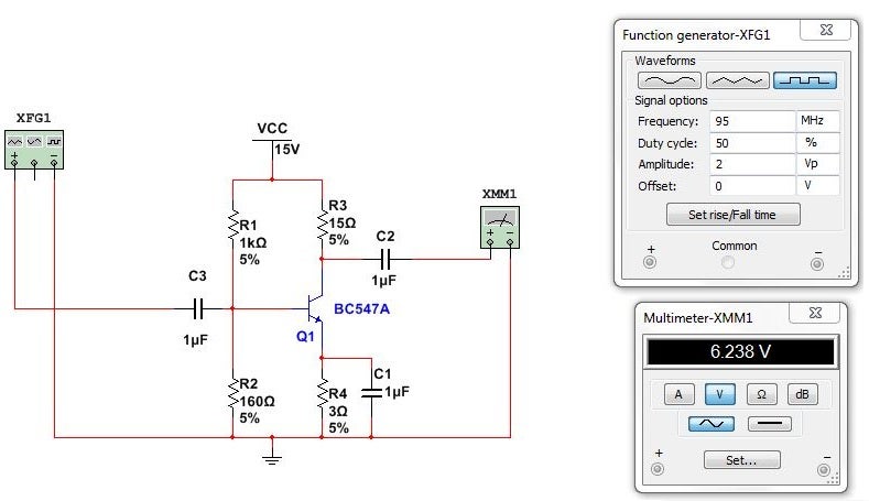
1 Transistors Bipolar Junction Transistors BJT Transistor Basics A Bipolar Junction Transistor is a three layer npn or pnp semiconductor device. The BJT is a three terminal device and it comes in two different types. In the previous tutorial we saw that the standard. ESE319 Introduction to Microelectronics 2008 Kenneth R. How To Design Common Emitter Amplifier 7 Steps With Pictures Instructables.
 Source: atakansarioglu.com
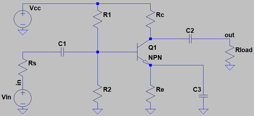
201 shows a class A common emitter amplifier but without its component values. Amplification of AC signal can be only done in active region of transistorTo operate transistor in active region Q-point need to be fixed at the center of DC load lineThe red line in the graph indicates DC load lineFixing Q-point at center of DC load line gives maximum amplificationTo fix Q-point at the center of DC load line designing of CE amplifier with correct choosing of resistor and. A transistor is an electronic component that has three terminals. Common Base BJT Amplifier. Transistor 101 Practical Common Emitter Amplifier Design Tech Inside.
 Source: electronics-lab.com
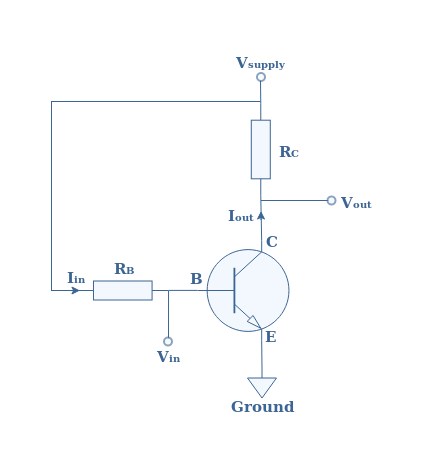
In todays tutorial we will have a look at BJT as an Amplifier. For any network that have coupling capacitors the source and load resistance do not affect the dc biasing levels. In todays tutorial we will have a look at BJT as an Amplifier. Terminals are base-emitter collector and base. Common Emitter Amplifier Electronics Lab Com.
 Source: youtube.com
201 shows a class A common emitter amplifier but without its component values. Amplifier design which mainly involves setting DC voltages. Egative type and a. The BJT is a three terminal device and it comes in two different types. Bjt Amplifier Design Part 1 Dc Biasing Youtube.
 Source: emagtech.com
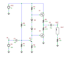
A transistor is an electronic component that has three terminals. Differential amplifiers have high common mode rejection ratio CMRR and high input impedance. The BJT is fabricated with three separately doped regions. That becomes possible due to the many emitter follower stages involved within an amplifier circuit. Advanced Tutorial Lesson 3 Investigating Audio Power Amplifiers Emagtech Wiki.
 Source: electronics-tutorials.ws
You basically make a crude amplifier with a high gain and enough bandwidth and use feedback to get the gain you actually want. Lopresti 2006 updated 01Oct08 KRL 2 Basic Single BJT Amplifier Features CE Amplifier CC Amplifier CB Amplifier. Amplification is process through which weak input signal is amplified. 1 Transistors Bipolar Junction Transistors BJT Transistor Basics A Bipolar Junction Transistor is a three layer npn or pnp semiconductor device. Npn Transistor Tutorial The Bipolar Npn Transistor.


